


You are handed a tender document, an edital in Brazilian public procurement, that requires the design to be delivered in IFC. You open Civil 3D, look for the export button... and find yourself in almost uncharted territory: thin documentation, next to nothing in Portuguese, and a model that comes out the other end as a heap of unnamed generic solids. If that scene sounds familiar, this guide is for you.
IFC (Industry Foundation Classes) grew up in the world of buildings: walls, doors, slabs, columns. For two decades the schema simply had no vocabulary for linear infrastructure. A highway exported to IFC 2x3 or IFC 4 turned into a collection of IfcBuildingElementProxy — geometry with no semantics whatsoever. The software at the receiving end saw solids, but had no idea which ones were carriageway, shoulder, cut or fill.
The practical result: highway infrastructure BIM fell years behind building BIM, and became the preserve of a very small group of practitioners. In Brazil and Portugal it is closer to folklore — everyone has heard of it, hardly anyone has seen it work end to end.
In 2024, IFC 4.3 was published as an international standard (ISO 16739-1:2024). It is the first release of the schema with native entities for infrastructure: roads, railways, bridges, ports and the geometric alignment that stitches all of it together. For the first time, the exported model can know what it is:
| Design element | IFC 4.3 entity |
|---|---|
| Road (the works as a whole) | IfcRoad |
| Segment, carriageway, shoulder, footway | IfcRoadPart (ROADSEGMENT, CARRIAGEWAY, SHOULDER...) |
| Alignment | IfcAlignment |
| Pavement and its courses | IfcPavement / IfcCourse |
| Cut and fill | IfcEarthworksCut / IfcEarthworksFill |
| Traffic sign | IfcSign |
| Kerb | IfcKerb |
| Bridge and its parts | IfcBridge / IfcBridgePart |
Look at the pattern behind that table, because it is the key to reading any infrastructure model. IFC 4.3 generalised the idea of the building: IfcBuilding is no longer the centre of the schema, just one special case of IfcFacility — the works, whatever they happen to be. Alongside it sit IfcRoad, IfcBridge, IfcRailway and IfcMarineFacility. And each one has its own part: IfcRoadPart, IfcBridgePart and the rest are all IfcFacilityPart.
That gives you the backbone of every infrastructure model, and it does not change from one project to the next:
IfcProject — the project: units, georeferencing, authorship
└─ IfcSite — the site
   └─ IfcFacility — the works   (IfcRoad, IfcBridge, IfcRailway, IfcMarineFacility…)
      └─ IfcFacilityPart — a part of it   (IfcRoadPart, IfcBridgePart…)
         └─ the objects   (pavement, earthworks, signage…)
All four tiers are tied together by the same relationship, IfcRelAggregates — including the first, from the project down to the site. Learn it once and the same backbone serves the road, the flyover and the rail yard of the same contract. That is why every tree in the rest of this post starts the same way.
The best way to understand IFC 4.3 is to do what we do on site: build it in stages. We start with the simplest case — a pavement structure — and add complexity until we hit the point where almost every IFC workflow falls apart.
In IFC, every physical object lives inside a spatial hierarchy — think of it as the object's engineering address: the site (IfcSite), the highway (IfcRoad) and the segment (IfcRoadPart). At the end of that address sit the physical elements: the pavement (IfcPavement) and each of its courses (IfcCourse):
IfcProject — Sample Highway dualling
└─ IfcSite — Project site
   └─ IfcRoad — Sample Highway   (an IfcFacility)
      └─ IfcRoadPart.ROADSEGMENT — Segment 01   (an IfcFacilityPart)
         └─ IfcRoadPart.CARRIAGEWAY — Carriageway
            └─ IfcPavement.FLEXIBLE — Pavement
               ├─ IfcCourse — Surface course (hot-mix asphalt)
               ├─ IfcCourse — Base course (graded crushed stone)
               ├─ IfcCourse — Subbase
               └─ IfcCourse — Capping layer
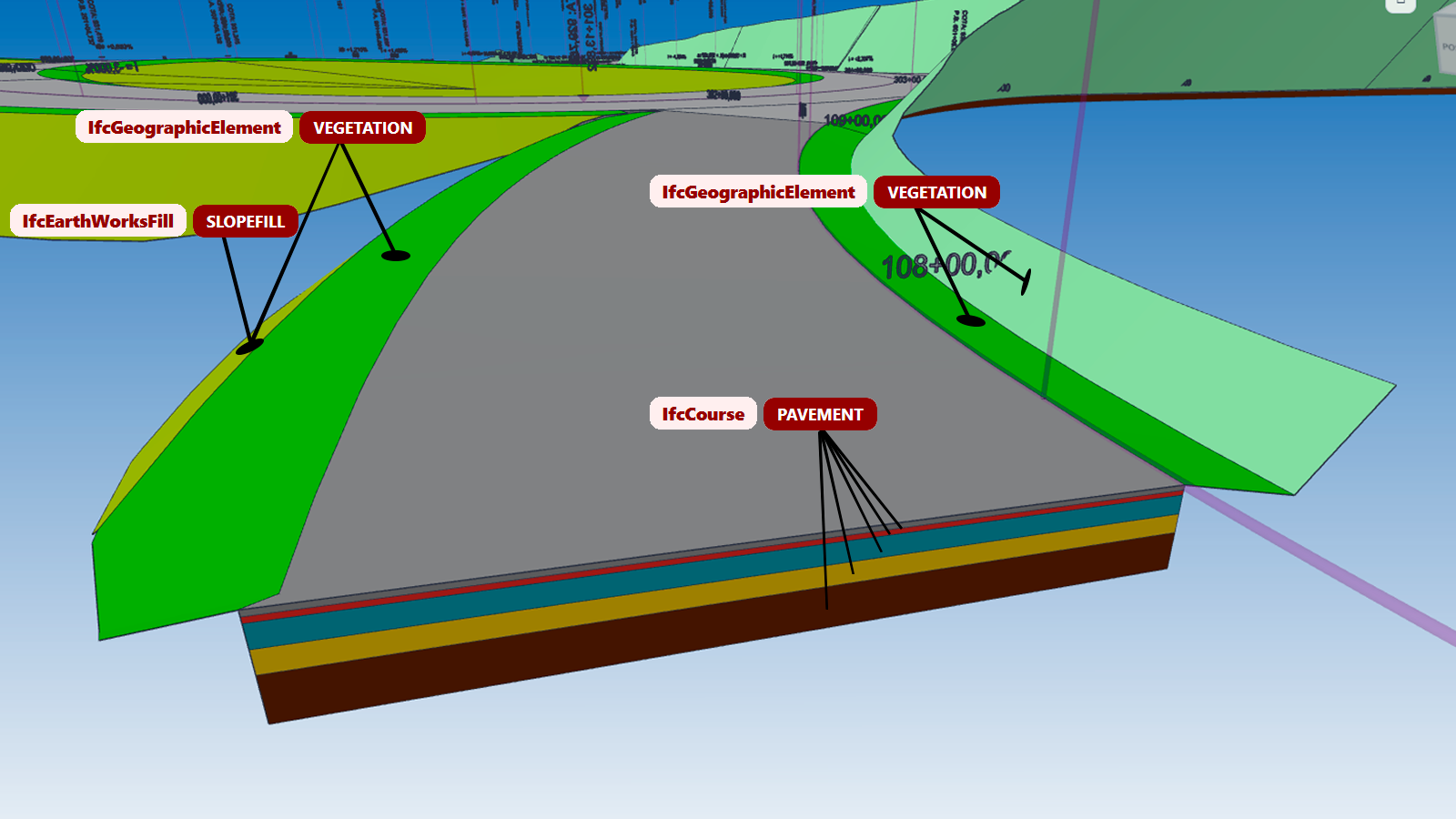
Notice what that buys you: the surface course stops being "solid 47" and becomes a named course, in a pavement, in a carriageway, in a segment, on a highway. A cost-estimating package can total the hot-mix asphalt volume for the whole of Sample Highway with a single query — without opening the drawing, without guessing anything from a CAD layer name.
Now let's widen the model to take in the biggest item on any highway by volume — and by cost. IFC 4.3 gives earthworks dedicated entities: cut is IfcEarthworksCut, fill is IfcEarthworksFill, with the type EMBANKMENT for the embankment body:
IfcProject — Sample Highway dualling
└─ IfcSite — Project site
   └─ IfcRoad — Sample Highway
      └─ IfcRoadPart.ROADSEGMENT — Segment 02
         ├─ IfcEarthworksFill.EMBANKMENT — Embankment body
         ├─ IfcEarthworksFill.SLOPEFILL — Fill slope
         ├─ IfcGeographicElement.VEGETATION — Vegetation cover on the cut slope
         ├─ IfcGeographicElement.VEGETATION — Vegetation cover on the fill slope
         └─ IfcGeotechnicalStratum — Natural ground
            ╌╌╌ IfcEarthworksCut.CUT — Cut   (not a child: it voids the ground, IfcRelVoidsElement)
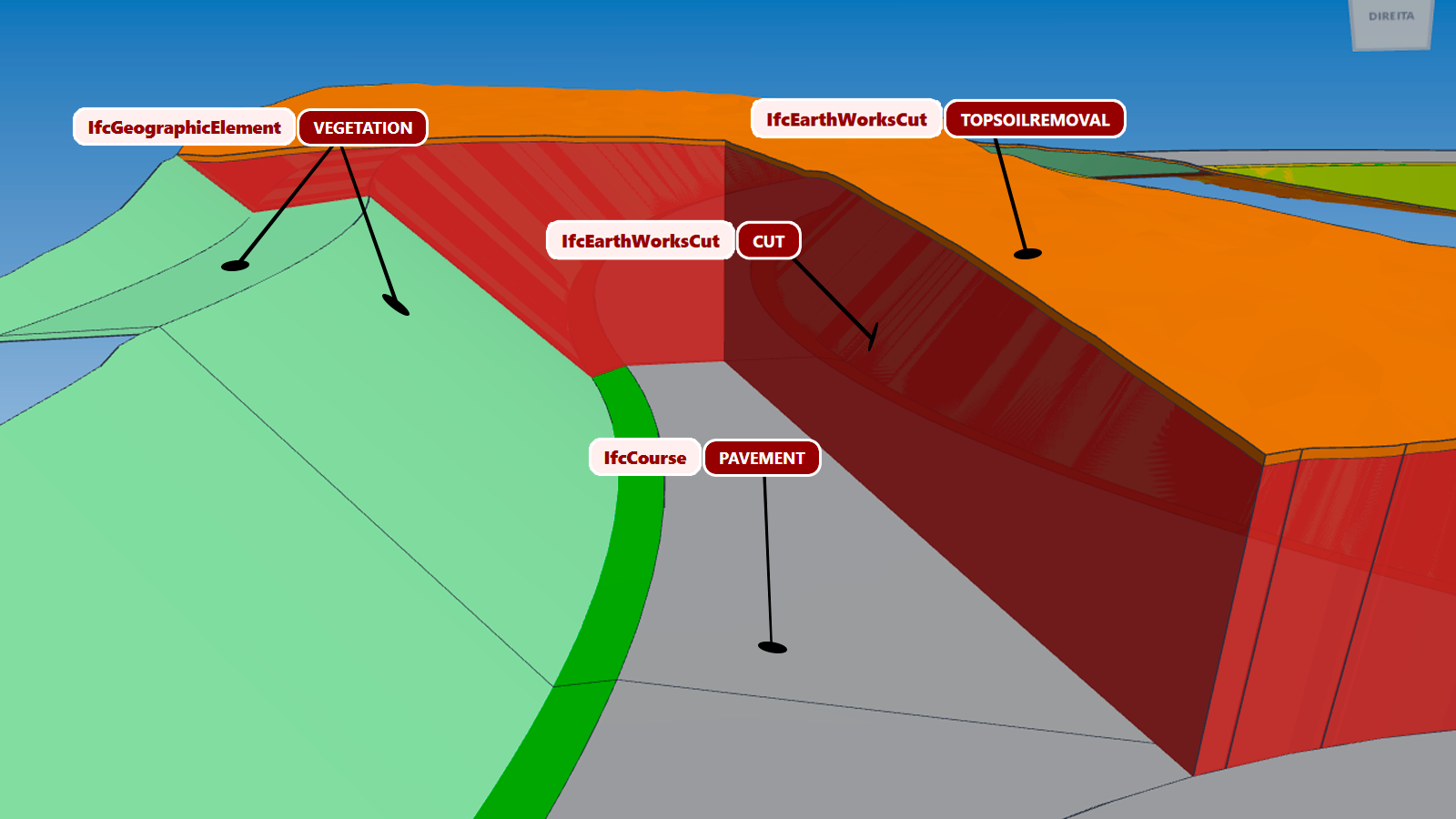
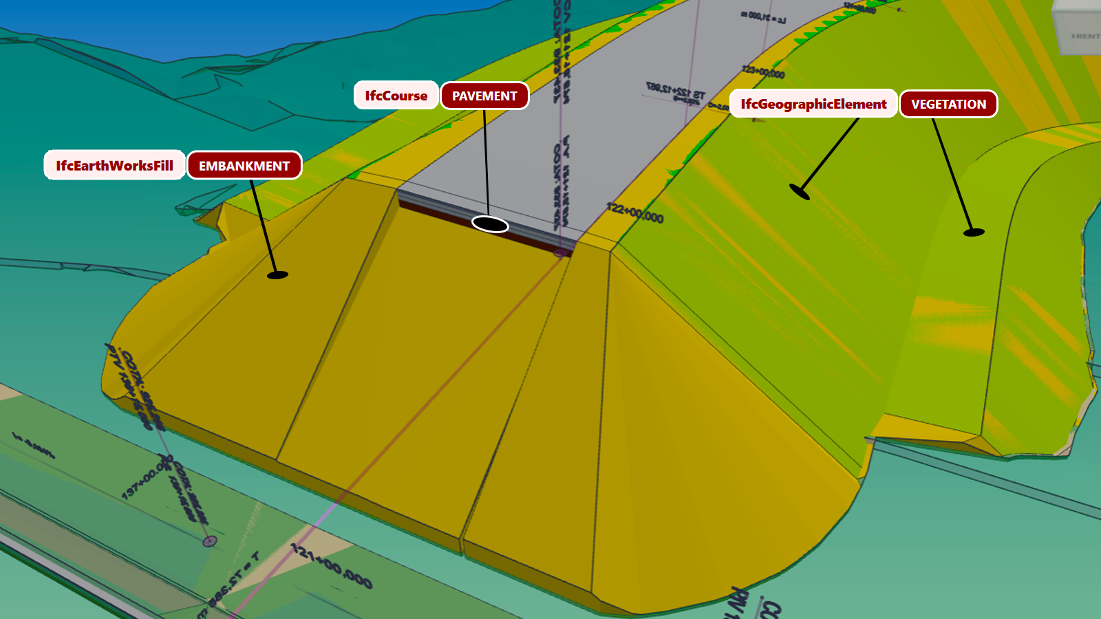
Click any image to enlarge.
Look at the fill slope: it is not "just another fill solid" — it is an IfcEarthworksFill of type SLOPEFILL, which the schema defines as side slope fill: the lateral wedge sitting against the embankment body. Watch the geometry, because this one is easy to get wrong: SLOPEFILL is not a layer laid on top of the fill — it is the lateral portion of the mass itself, built with a different material or compaction from the core.
And watch out for a common mix-up here: SLOPEFILL is not a material — it is a function.
IFC splits into four independent levels what site staff usually pack into a single word. Pull them apart and most classification questions answer themselves:
| Level | Answers the question | In the example fill |
|---|---|---|
EntityIfcEarthworksFill | What is this object? | A volume of material added to the ground |
PredefinedType.EMBANKMENT · .SLOPEFILL | What role does it play in the works? | Embankment body · lateral side slope wedge |
MaterialIfcMaterial | What is it made of? | Selected fill, rock fill, sand… |
Property setPset_ · Qto_ | What data does it carry? | Volume, degree of compaction, CBR |
The four vary independently. The same SLOPEFILL can be selected fill on one job and rock fill on the next with no change to the classification — swapping the material must never spawn a new entity. It is the most expensive mistake you can make here, because it multiplies classes in the model and breaks quantity take-off totals.
Which brings us to the question that decides whether the slope deserves to exist in the tree: was it built as a mass distinct from the embankment body? If the side slope is placed in selected fill, with its own material or compaction, then yes — it is an element with a quantity take-off of its own. If the fill is homogeneous, the whole body is a single EMBANKMENT and the "slope" is merely its geometric face; modelling a separate solid there would invent material that does not exist — the same honesty test as the cut slope.
Vegetation cover, meanwhile, is a classic trap: the temptation is IfcCourse, but the schema defines a course as a layer of processed granular material (crushed stone, sand, asphalt) — right for rip-rap (IfcCourse.PROTECTION or ARMOUR), wrong for grass. For vegetation cover the correct classification is IfcGeographicElement.VEGETATION, whose definition — "plant life or plant cover" — expressly includes grasses. Classified that way, the hydroseeding area becomes a quantity you can query in the model, instead of a sum worked out separately in a spreadsheet.
So what about the cut slope? The answer is not our convention: it is in the schema itself. Here is the complete model of an earthworks segment in IFC 4.3 — from project down to resources, with the relationships that tie it all together:
The segment is the pivot: everything made of matter hangs off it through IfcRelContainedInSpatialStructure. The cut does not — it is a void, and the schema forbids a void from entering the spatial structure. Note too that there is a single box for IfcEarthworksFill carrying two roles: the role changes, never the class.
← drag the diagram sideways →
So, the cut slope. Here IFC captures an asymmetry every earthworks engineer knows: in fill, the slope is a mass you build — which is why it exists as a solid in its own right (SLOPEFILL). In cut there is no new solid: the slope face is existing ground laid bare by the excavation — and the excavation itself is IfcEarthworksCut of type CUT, which the schema provides for road and rail cuttings.
And do not give in to the temptation to reuse SLOPEFILL here for symmetry: fill, by the schema's own definition, is added material — "created by earthworks activities to build the subgrade or raise the ground level". The face of a cut slope was not added, it was uncovered. (The "back slope fill" that appears in the SLOPEFILL definition is fill placed against the slope — a berm, say — not the excavated face.) If you need the cut slope with a quantity take-off of its own, it is still excavation: a second IfcEarthworksCut, not a fill.
The only new thing entering the model is the vegetation cover applied over that face — again an IfcGeographicElement.VEGETATION.
And where does the cover applied to the slope after excavation belong — inside the cut? No, and here the schema itself ends the argument: in IFC 4.3, IfcEarthworksCut is not a solid, it is a subtraction feature element, defined literally as "the void resulting from the removal of material". A void hosts no physical element at all — there is no "inside the cut". The cover, on the other hand, is a real product, built on the exposed face once the excavation is finished: it lives on its own in the spatial structure, on the segment, as a sibling of the earthworks solids.
The same reasoning holds for the fill slope. There a solid does exist — but the cover is applied over it, it is not a constituent layer of the mass, and nesting it would be a declaration of composition: grass is not part of an embankment. In both cases, the link "this cover sits on that slope" is recorded through IFC's own properties and relationships, not through the spatial hierarchy.
The concept is the same as for pavement — what changes is the scale of the problem. In a real corridor every material generates its own solids, segment by segment: cut, fill, soft soil removal, vegetation cover... That is hundreds of objects to classify in a single project. Remember that pain: it is what separates people who "have tried exporting IFC" from people who deliver.
So far, every object in the model has been a single thing — one course, one cut solid. But a road is full of objects that are assemblies: a traffic sign is a sign plate + a post + a footing. A sign gantry, a traffic signal, a safety barrier with its end terminals — same story.
And this is where the deepest problem in the Civil 3D IFC workflow lives: as far as the native export is concerned, a block is a single IFC object. The whole sign comes out lumped together as one generic element. So much for a post quantity take-off, so much for footings in the model, so much for clash-checking the footing against the drainage.
IFC 4.3 has the right answer to this: IfcElementAssembly with type SIGNALASSEMBLY — the assembly as one node, and every part as an element of its own inside it. A properly exported R-24a sign shows up in the viewer exactly like this:
IfcProject — Sample Highway dualling
└─ IfcSite — Project site
   └─ IfcRoad — Sample Highway
      └─ IfcRoadPart.ROADSIDE — Roadside of Segment 01
         └─ IfcElementAssembly.SIGNALASSEMBLY — R-24aESQ_3
            ├─ IfcSign — L-PLACA (the sign plate)
            ├─ IfcMember — L-POSTE (the post)
            └─ IfcFooting — L-SAPATA (the footing)
Every part individually selectable and quantifiable, with its colour and style preserved, and the whole assembly nested under the right segment of the road. That is the kind of granularity a BIM coordinator spots in the first model audit.
IfcElementAssembly assemblies does not exist in the native Civil 3D export — there, a block is always a single IFC object. As far as we know, SCENG Tools is the only tool that delivers elements as hierarchical assemblies (signs, sign gantries, and so on) straight out of Civil 3D. The tree above comes from a real export.
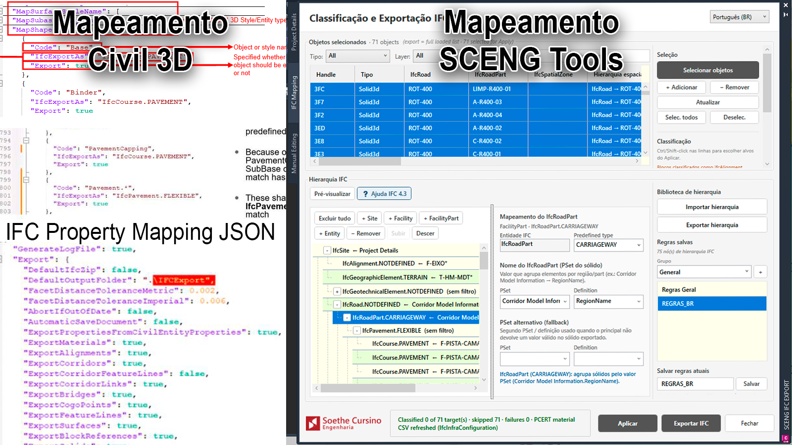
You have just seen what a well-built IFC 4.3 model needs. Autodesk ships an official add-on (IFC 4.3 Extension for Civil 3D, installed separately) that handles the export — but exporting was never the problem. Classifying is. The native routes for telling the software "this solid is an IfcCourse" are, shall we say, spartan:
IfcObject Properties and a property IFC::IfcExportAs carrying the entity value (e.g. IfcRoadPart.ROADSEGMENT). One wrong character and the classification is ignored — silently.IfcInfraExportMapping.json full of regular expressions, with no user interface and next to no documentation.Now multiply that by the hundreds of solids in the earthworks section above — and remember that assembly decomposition simply does not exist on the native route. That is why so many people give up halfway.
That exact pain, felt on our own projects, is what led to the IFC 4.3 Manager in the SCENG Manager module. The idea: you define engineering rules, and the plugin deals with the schema paperwork.
Classify by layer, style or object name, with wildcards — a single L-PLACA* rule catches every sign in the project at once. As you edit the rule, a live counter shows how many objects in the drawing match it, before anything is applied.
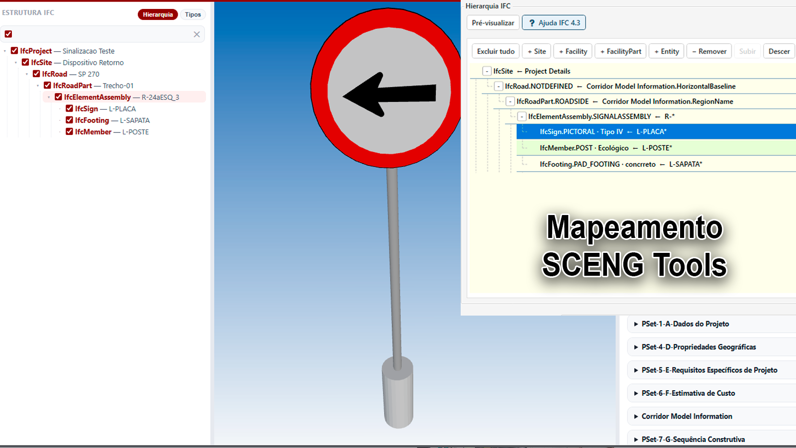
The export builds the Site → IfcRoad → IfcRoadPart → objects tree, and the names come from the project's own Property Sets: the highway arrives on the other side as "Sample Highway — Main Carriageway", not "Corridor (1)". The same logic carries over to other domains — a flyover classified as IfcBridge nests as a bridge, not as a road.
The R-24a sign tree you saw above came out of Civil 3D exactly like that. One rule on the block defines the assembly (IfcElementAssembly.SIGNALASSEMBLY) and child rules, driven by the block's internal layers, define the parts: sign plate, post, footing. The plugin decomposes, classifies, exports and cleans up on its own — without exploding your drawing.
Do not take our word for it: this is the IFC the plugin exported, opened right here in your browser. Expand the tree down to R-24aESQ_3: the sign arrives decomposed into L-PLACA, L-POSTE and L-SAPATA. Open full screen →
For the cases that break the rule, an object-by-object editing grid with undo/redo, kept in sync with the general rules.
Rules, hierarchy, model author and georeferenced base point are all saved as an IFC Project — a file you reuse on the next drawing of the same works, or share with the team. Set it up once, export the whole job.
In Brazil, the second phase of Decree 10.306/2020, the federal BIM mandate, has been in force since 2024, requiring BIM for federal public design and construction contracts — and DNIT, the federal highway agency, and the state DERs, the state highway departments, are already issuing tenders with explicit BIM requirements. In Portugal, standardisation is moving ahead through CT 197, the national BIM standards committee, and the European public procurement directive allows the client to demand BIM in tenders.
The consequence is simple: demand for IFC in infrastructure will grow faster than the supply of people who can actually deliver it. Master this workflow today and you have a rare competitive edge — tomorrow it will be a baseline requirement.
Put the three tiers together and this is how the entire project sits in the model — from the capping layer to the sign footing:
IfcProject — Sample Highway dualling
└─ IfcSite — Project site
   └─ IfcRoad — Sample Highway   (an IfcFacility)
      ├─ IfcAlignment — Main alignment
      ├─ IfcRoadPart.ROADSEGMENT — Segment 01
      │  └─ IfcRoadPart.CARRIAGEWAY — Carriageway
      │     └─ IfcPavement.FLEXIBLE — Pavement
      │        ├─ IfcCourse — Surface course (hot-mix asphalt)
      │        ├─ IfcCourse — Base course (graded crushed stone)
      │        ├─ IfcCourse — Subbase
      │        └─ IfcCourse — Capping layer
      ├─ IfcRoadPart.ROADSEGMENT — Segment 02
      │  ├─ IfcEarthworksFill.EMBANKMENT — Embankment body
      │  ├─ IfcEarthworksFill.SLOPEFILL — Fill slope
      │  ├─ IfcGeographicElement.VEGETATION — Vegetation cover on the cut slope
      │  ├─ IfcGeographicElement.VEGETATION — Vegetation cover on the fill slope
      │  └─ IfcGeotechnicalStratum — Natural ground
      │     ╌╌╌ IfcEarthworksCut.CUT — Cut   (voids the ground, not a child)
      └─ IfcRoadPart.ROADSIDE — Roadside
         └─ IfcElementAssembly.SIGNALASSEMBLY — R-24aESQ_3
            ├─ IfcSign — L-PLACA
            ├─ IfcMember — L-POSTE
            └─ IfcFooting — L-SAPATA
Every one of them came up in the examples above. Worth printing and keeping beside your monitor:
| Question | The rule it applies |
|---|---|
| Material, or function? | The PredefinedType describes the role in the works, not what the element is made of. SLOPEFILL is the side slope fill, whatever material it is built from. |
| Mass, or face? | Material actually placed becomes an element with volume. A face is just a boundary — which is why SLOPEFILL exists but a "cut slope" element does not: in a cut, the slope is the face of the void. |
| Part of it, or on top of it? | Nest only what the element is made of (the courses inside the pavement). Anything applied on top of another element goes in as a sibling — vegetation cover being the obvious example. |
| Was it built, or was it already there? | IfcEarthworksFill is material added; IfcEarthworksCut is the void left by excavation. Never declare fill where material was only removed. |
| Single part, or assembly? | A block whose parts have distinct functions becomes an IfcElementAssembly with every part classified — not one lumped solid. |
A model that answers those five questions well is already ahead of the vast majority of infrastructure IFC files in circulation.
IfcElementAssembly, with the individual parts kept separate) instead of being merged into a single solid?The IFC 4.3 Manager is part of the SCENG Manager module (PSet / IFC 4.3), which is also included in SCENG Full. If your Civil 3D is version 2026.2.2 or later, first check which plugin version to use.
The SCENG team — always innovating to make your work in Civil 3D easier.
Comments are open to registered users.
No comments yet. Be the first.